A chute keeps needing a patch in the same spot. One hopper liner wears through while the neighbouring plates still have useful life. A crusher develops an uneven wear pattern.
These problems raise an important maintenance question: why is that particular area wearing faster?
In mining and mineral processing equipment, wear often concentrates where material lands, slides against a surface or changes direction. However, there is no universal “first” wear point. The location depends on the equipment design, material characteristics, feed conditions and liner arrangement.
For maintenance teams, understanding these wear zones helps turn a recurring repair into a more informed maintenance decision.
What causes mining equipment wear?
Two common mechanisms are sliding abrasion and abrasive impact.
Sliding abrasion occurs when abrasive material moves across a surface, scratching and gradually removing material. Abrasive impact occurs when particles or rocks strike a surface. The speed, angle and mass of the incoming material influence the damage. A single liner can experience both mechanisms.
Think of a rock entering a chute: it can hit the impact plate, then slide down the chute floor. The first surface must withstand the strike; the next must resist repeated scraping.
That is why one liner specification may not suit every position in the same equipment.
Common mining equipment wear zones at a glance
The following are useful inspection priorities, rather than a fixed ranking of which component will fail first.
| Equipment | Common wear zones to inspect | What to look for |
|---|---|---|
| Chutes | Initial impact area, sliding surfaces and changes in direction | Localised thinning, grooves, deformation and recurring patches |
| Hoppers | Loading strike area, active flow paths, liner joints and feeder interfaces | Uneven thinning, channels along joints and exposed edges |
| Jaw crushers | Jaw plates and cheek plates | Worn tooth profiles, uneven wear and damaged plates |
| Cone crushers | Mantle and concave or bowl liner | Uneven wear around the chamber or concentrated wear bands |
| Conveyor transfer points | Receiving impact area and skirtboard liners | Localised liner wear, damaged containment and changes in spillage |
These priorities reflect the impact, abrasion, joint wear and feed distribution issues described in equipment manufacturers’ guidance.
1. Chutes: where material lands and changes direction
The first surface in the path of falling rock is an obvious place to investigate.
Metso identifies high impact transfer areas as locations where liners can experience significant impact wear and sliding abrasion. These concentrated wear spots can become recurring repair points and drivers of maintenance shutdowns.
After the initial strike, follow the material’s route through the chute. Inspect the sliding surfaces and areas that redirect the stream.
A practical question: does the same small area need replacing while most of the surrounding liner remains serviceable?
If so, review the material trajectory and chute geometry alongside the liner specification. Replacing the plate addresses the damage; understanding the flow helps explain why it keeps happening.
Engineered rockboxes and material retaining liner designs can protect surfaces by encouraging material to move against retained material. Metso uses this principle in its Rockbox and Wearback systems. Suitability depends on the application and flow requirements.
2. Hoppers: follow the flow and check the joints
A hopper’s wear pattern should be assessed against where material enters and how it moves towards the outlet.
Useful inspection areas include the loading strike zone, surfaces carrying the moving stream, liner edges and the transition into the feeder. Their relative importance will vary with the hopper’s geometry and operating conditions.
Pay particular attention to liner joints.
Metso identifies material tracking along joint lines as a cause of preferential wear in stockpile hoppers and chutes. Its guidance also describes vertical wash lines in bins and horizontal wash lines in feeder side wall liners.
In simple terms, the joint can become a concentrated wear path while the centre of the plate still looks relatively healthy.
During inspection, compare the remaining thickness around joints and edges with the wider liner surface. A plate that appears sound in the middle may still have a vulnerable boundary.
3. Crushers: wear patterns depend on the machine
Crusher wear needs a more specific approach because the wear components form part of the crushing chamber itself.
Jaw crusher wear
Jaw plates and cheek plates are key wear components. Metso’s guidance for its rotatable jaw plates identifies the lower tip of the fixed jaw and the central area of the moving jaw as locations where more severe wear can occur because of the crushing movement.
This is a useful example of why “check the bottom first” is too simple a rule. Different parts of the chamber experience different wear patterns.
Inspect the tooth profile and wear distribution, and follow the manufacturer’s criteria for rotation and replacement.
Cone crusher wear
In a cone crusher, the mantle and concave or bowl liner are major wear surfaces.
Uneven wear should prompt a review of feeding conditions as well as liner selection. Sandvik identifies poor feed conditions as a major contributor to uneven liner wear. Metso also notes that feed which is too small for the selected cavity can increase wear at the bottom of the liners.
The wear pattern can reveal an operating problem. Replacing liners without reviewing feed distribution or chamber suitability may leave the cause unresolved.
Specialist crusher wear parts require the correct profile, alloy and fit for the machine. They should not be treated as interchangeable with general purpose cut wear plate.
4. Conveyor transfer points: inspect impact and containment together
At a transfer point, inspect both the receiving impact area and the liners that contain the material along the loading zone.
Skirtboard wear liners help shield the sealing system from the material load. Martin Engineering also identifies material bounce and trapped lumps as considerations in transfer point liner design.
Look beyond the most visibly worn plate. Review whether material is loading centrally and whether the transfer arrangement guides it smoothly onto the receiving belt. Metso’s transfer chute guidance highlights controlled flow and centred loading as design objectives.
A change in spillage is worth investigating, but it does not prove that the liner alone is responsible. Check the wider loading and containment arrangement.
How maintenance teams can track wear more effectively
A useful wear record shows where material is being lost and how quickly that pattern is changing. During planned inspections, under the site’s isolation and access procedures:
- Map liner positions. Give each plate or zone a clear reference.
- Measure consistently. Record remaining thickness at repeatable locations using a suitable method.
- Photograph the same areas. Include impact zones, joints, edges and attachment points.
- Record operating changes. Note changes in feed, throughput or material characteristics.
- Use defined replacement limits. Follow OEM requirements and site engineering criteria rather than waiting for perforation.
Comparing successive inspections can help identify which areas need closer monitoring and which replacement components should be prepared before the next shutdown.
Choosing wear plate for the application
Hardness matters, but it is only part of material selection. Impact resistance, toughness, thickness, support and fabrication requirements also need consideration. SSAB’s guidance emphasises selecting an appropriate balance of wear resistance and other material properties for the application.
For maintenance planning, start with the damage mechanism and approved component specification. Avoid assuming that a harder or thicker plate will automatically solve every recurring wear problem.
Wear plate supply and processing from Steel Plate Solutions
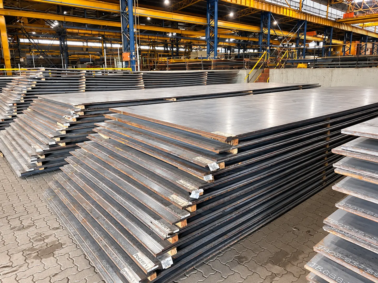
Steel Plate Solutions supports mining and engineering customers with steel plate supply and processing from Richards Bay and Germiston.
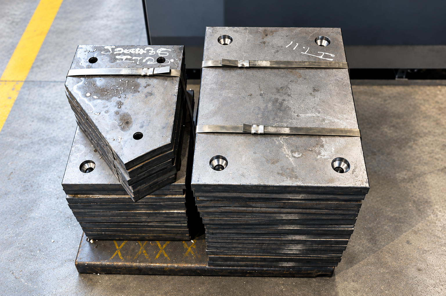
Our product range includes NM400, NM450 and NM500 wear plate, with processing services including cutting, bending, rolling, drilling and countersinking to customer requirements.
For replacement steel liners, send the SPS team your approved drawings, material grade, thickness, quantities and hole details. Where an existing liner has worn significantly, confirm its original dimensions and specification before manufacturing a replacement.